Abstract
Moving transcatheter valve intervention towards atrioventricular (AV) valves implies increasing complexity. Some of the knowledge that has been generated during the development of mitral devices can be applied to the tricuspid valve (TV). A deep understanding of the peculiar anatomy of the TV and of the right heart chambers, with differences and similarities between the two AV valves, is fundamental to overcoming the specific challenges related to transcatheter TV therapies. The aim of this report is to explore similarities and differences between the mitral and tricuspid valve apparatus, and their interventional implications.
Abbreviations
AV: atrioventricular
ICE: intracardiac echocardiography
LA: left atrium
LAA: left atrial appendage
LV: left ventricle
LVOT: left ventricular outflow tract
MSCT: multislice computed tomography
MV: mitral valve
PM: papillary muscle
RA: right atrium
RAA: right atrial appendage
RV: right ventricle
RVOT: right ventricular outflow tract
TEE: transoesophageal echocardiography
TTE: transthoracic echocardiography
TV: tricuspid valve
Introduction
Transcatheter valve therapies have profoundly changed the treatment of heart valve disease over the last decade. While from an anatomical and technical standpoint the aortic valve could be considered “easy” to address, moving towards atrioventricular (AV) valves implies increasing complexity and a deeper knowledge of both function and anatomy. The development of transcatheter mitral valve (MV) therapies took longer, due to the structure of the MV complex and to the heterogeneity of pathology, which is also reflected in a more complex imaging. With the development of transcatheter tricuspid valve (TV) therapies, physicians are facing an even more challenging anatomical scenario. Some of the knowledge that has been generated during the development of mitral devices can be applied to the TV. However, a deep understanding of the peculiar anatomy of the TV and of the right heart chambers, with differences and similarities between the two AV valves, is fundamental to overcoming the specific challenges related to transcatheter TV therapies.
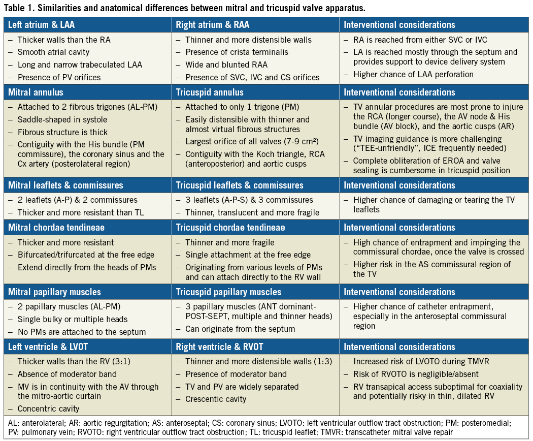
The aim of this report is to explore similarities and peculiar anatomical differences between the MV and TV apparatus, and their implications with regard to transcatheter treatments (Table 1).
LEFT ATRIUM, RIGHT ATRIUM
ANATOMICAL DESCRIPTION
Left atrium
The left atrium (LA) is the cardiac chamber that normally receives pulmonary venous drainage from the four pulmonary veins. Its septal surface is characterised by the flap valve of the fossa ovalis (septum primum), in contrast to the limbus (septus secundum) of the fossa ovalis present on the right atrioseptal surface (Figure 1). The left atrial appendage (LAA) is long and narrow, in contrast to the bluntness of the right atrial appendage (RAA), and is the best indicator that the atrium is morphologically an LA (Figure 2).
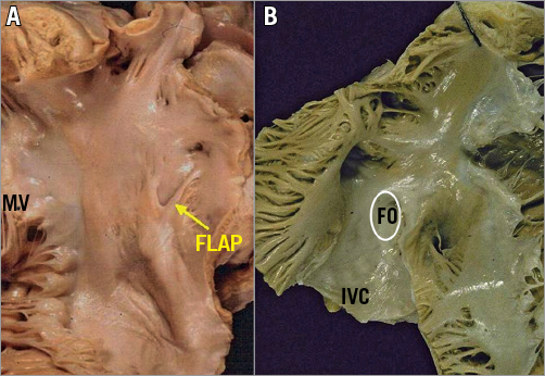
Figure 1. Comparison of atrial septal surfaces. A) The septal surface of the left atrium is characterised by the flap valve of the fossa ovalis (septum primum), in contrast to the limbus of the fossa ovalis (FO) present on the right atrioseptal surface (B). .
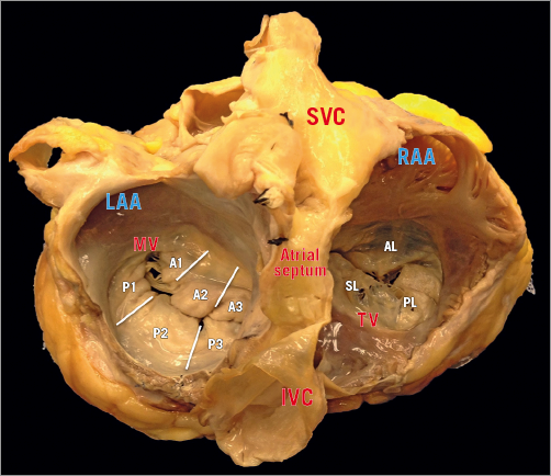
Figure 2. This specimen illustrates the different spatial relationships between the SVC and IVC, the interatrial septum and the two AV valves. Differently from the right atrium, there is no crista terminalis at the base of the LAA, which is the only trabeculated structure in the left atrium. Segmentations of MV leaflets: sections A1 and P1 represent the anterolateral scallops, A2 and P2 the middle ones, and A3 and P3 the posteromedial scallops.
Right atrium
The RA consists of a curved posterior groove continuous with the superior and inferior vena cava, a flat interatrial septum, a trabeculated dome, and the TV. The posterior groove is a smooth and thin wall separated by the trabeculated wall by a ridge of muscle, which is the crista terminalis, extending from the superior to the inferior vena cava1,2.
The RAA consists of the anterolateral triangular part of the RA; it is demarcated on the endocardial surface by the crista terminalis, which distinguishes it from the smooth-walled venous portion. The crista terminalis provides the origin for the pectinate muscles, the largest and most prominent being the so-called tenia sagittalis3. The distal border of the RAA is the smooth-walled vestibule around the TV orifice. In comparison to the LA, the RA has thinner walls and dilates more easily given the same degree of pressure overload.
INTERVENTIONAL CONSIDERATIONS
Different interventional accesses to the LA have been adopted, including direct transatrial, transapical, transarterial retrograde and transseptal.
The transseptal access is currently the preferred route for most transcatheter MV repair techniques and its usage is quickly increasing for mitral valve-in-valve and valve-in-ring procedures, since it has shown superior safety compared to the apical one4,5. Transapical access is the most used approach for native MV replacement and for transcatheter neochordal implantation.
The transseptal route is used for MitraClip® (Abbott Vascular, Santa Clara, CA, USA) implantation and for direct annuloplasty with the Cardioband device (Edwards Lifesciences, Irvine, CA, USA). Both of the devices are delivered through a large (24 Fr) steerable guiding catheter, which allows the operator to reach the anatomical therapeutic target with a high level of precision, which is required to ensure safety and efficacy.
The location of the transseptal puncture is fundamental to ensure precision, since a specific therapeutic target could be extremely challenging or even impossible to reach with a proper trajectory, if the puncture is performed in the wrong location (e.g., too high or too low). Operators should be familiar with the anatomical structures in proximity to the interatrial septum: in case of a too anterior or too posterior puncture, the ascending aorta or the posterior LA wall can be punctured and injured. Procedural imaging with transoesophageal echocardiography (TEE) is the key to performing precise and safe transseptal puncture in complex structural interventions. Once the guiding catheter has been introduced into the LA, the septum gives adequate support and optimal stabilisation to the catheter itself, which allows the operators a really controlled and predictable steering. Specific anatomical considerations are required in the presence of an aneurysmatic fossa ovalis or in the presence of a “floppy” interatrial septum. In such an anatomical context, the support given by the interatrial septum to the catheter is reduced, due to its high mobility. This lack of support typically results in a shifting of the guiding catheter towards the annular plane, simulating a too low transseptal puncture. Therefore, operators should perform a higher puncture in the presence of this anatomy.
Navigation in the LA can be extremely challenging and potentially dangerous in the presence of a small LA, due to a reduced degree of movement, with increased risk of perforation, impingement and bleeding. The structures at higher risk are the LAA and the pulmonary veins. In particular, the LAA is located anteriorly to the fossa ovalis, and is easy to reach when crossing the septum if the atrium is not enlarged. Similarly to the MV, the TV is commonly approached antegradely. The most used approach is currently the transfemoral one through the inferior vena cava (IVC), while some devices are delivered through a transjugular approach. Since the TV is approached without transseptal puncture, the support that is given from the interatrial septum to the catheter in transseptal MV procedures is missing, resulting in a complete lack of stabilisation. Lack of septal support results in diving into the RV and lack of coaxiality. This represents a major issue, making navigation in the RA more challenging and less controlled. A peculiar difference between the two atria is represented by the atrial appendage: the RAA is large and well integrated into the atrial chamber, and it offers reduced risk during catheter navigation, compared to the risk of LAA perforation during MV procedures. However, a risk of injuring the RAA is present if the device is pushed out from the guiding catheter in an uncontrolled way.
MITRAL AND TRICUSPID ANNULI
ANATOMICAL DESCRIPTION
The mitral annulus
The mitral annulus is reinforced at each extremity of the base of the anterior leaflet by two dense triangular fibrous structures, the anterolateral (or left) and the posteromedial (or right) fibrous trigones. The MV annulus has a 3D saddle-shaped configuration and its shape varies through the cardiac cycle6. Four anatomical structures close to the mitral annulus are at risk of injury during interventional procedures:
a) the circumflex artery, which runs posteriorly and could be injured, especially during annuloplasty;
b) the coronary sinus, which skirts the attachment of the posterior leaflet;
c) the bundle of His which is located near the right trigone (medial commissure);
d) the non-coronary and left coronary aortic cusps which are in close relationship with the base of the anterior leaflet, the so-called mitro-aortic fibrous continuity (there is a 6-10 mm safety zone in this area).
The tricuspid annulus
The right AV junction delineates the change between the RA and the TV leaflets (Figure 3). As opposed to the mitral one, the tricuspid annulus is tiny and difficult to identify and delimitate, even on surgical or anatomical inspection, and annular calcifications are almost never observed (Figure 4). In pathologic conditions, the TV annulus tends to become planar. Development of functional TR is conventionally classified into three progressive stages: the initial annular dilatation, the progressive annular dilatation leading to lack of leaflet coaptation and, ultimately, the RV dilatation and dysfunction, with TV tethering. Three anatomical structures are at risk of injury during interventional procedures:
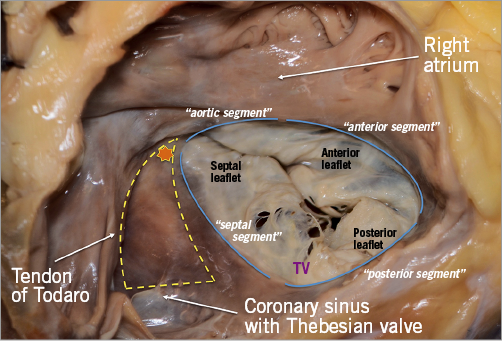
Figure 3. The TV has the annulus fibrosus deeper and 2 mm external to the hinge, almost a virtual structure. Yellow triangle depicts the triangle of Koch, which is delineated by the base of the septal leaflet, the tendon of Todaro (a fibrous extension between the Thebesian valve and the Eustachian valve) and the orifice of the coronary sinus. The AV node (star) is the most likely area to produce heart block.
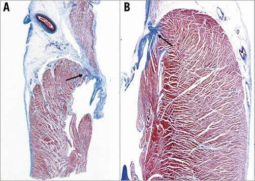
Figure 4. Histology of the atrioventricular sulcus showing the location of the fibrous annulus. A) Right AV junction, tricuspid valve; B) left atrioventricular junction, mitral valve.
a) the non-coronary sinus of Valsalva, in particular the commissure between the non-coronary and the right coronary aortic cusp (especially during annuloplasty procedures);
b) the bundle of His, which penetrates the central fibrous body and runs underneath the membranous septum 3 to 5 mm from the anteroseptal commissure (the landmark of the His bundle) (Figure 5);
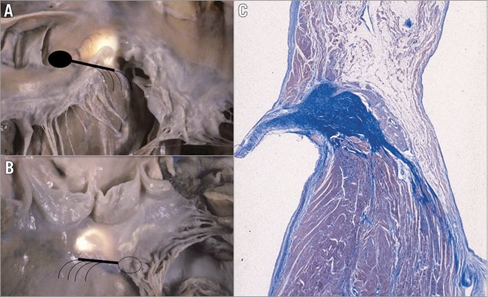
Figure 5. The specialised AV conducting tissue is located in correspondence to the membranous septum. A) Right side view; B) left side view. The landmark of the atrioventricular bundle from the left side is the continuity between the aortic and mitral valve, adjacent to the membranous septum (translucent area), which is located underneath the interleaflet triangle between the right and posterior non-coronary cusps. Note the subendocardial course of the left bundle branch (dotted lines). C) Histology of the normal atrioventricular conducting tissue shows that the atrioventricular node is located on the right side of the central fibrous body.
c) the right coronary artery, coursing down the right AV groove and surrounding anteriorly the anterior TV leaflet.
INTERVENTIONAL PERSPECTIVES
The more anterior location of the TV compared to the MV makes intraprocedural TEE guidance particularly challenging in tricuspid procedures. In some circumstances, a combination of TEE, transthoracic echocardiography (TTE) and intracardiac echocardiography (ICE) is needed to obtain adequate imaging quality. While computed tomography (CT) and TTE are used for preoperative diagnosis, intraprocedural guidance is mostly dependent on fluoroscopy and TEE, which provide high-quality images7,8. ICE guidance alone can be adopted for TV procedures9, although it has been adopted since the very beginning in combination with TTE and TEE. The major interventional issue related to the TV compared to the MV is its larger orifice (Figure 2, Figure 3). If, in normal conditions, the TV can already reach up to a 9 cm2 area, this will be much larger in the presence of functional TR. In such a situation, the regurgitant orifice area is often larger than 1 cm2 (more than double that in the mitral position), usually central and with a larger coaptation gap compared to the MV. Therefore, a complete obliteration of the regurgitant area can be extremely cumbersome with the current repair devices. Large anatomy and the absence of annular calcifications are probably the two most important challenges to overcome to obtain sealing with a replacement device in the TV position compared to the MV. The proximity of other cardiac structures has interventional implications in both the mitral and the tricuspid position. A peculiarity of the TV is the contiguity of the AV node and the His bundle, which is located in the proximity of the septal TV annulus, close to the anteroseptal commissure (the most common therapeutic target in MitraClip tricuspid procedures). In fact, an acute and complete AV block can be induced just by the contact of any device with the His bundle, due to its compression. In selected cases, a prophylactic intravenous temporary pacemaker (PM) implant should be considered. Furthermore, since TV annuloplasty requires longer and incomplete rings, a higher risk of right coronary injury and/or annular dehiscence should be taken into account. Currently, established universal anatomical criteria guiding the choice between a TV repair or replacement, beyond surgical experience, are not available. The risk of coronary damage during interventional procedures is mainly present in annuloplasty procedures, and is highly dependent on the coronary anatomy and dominance of the specific patients. The different relationship between the circumflex artery and the right coronary artery with the MV and TV, respectively, is illustrated in Figure 6.
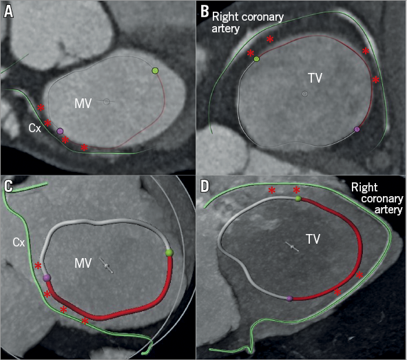
Figure 6. Cross-sectional view of the three heart valves seen from above with the atria removed. Advanced editing (digital coronary reconstruction and manual segmentation of the AV annuli) of a CT scan to assess the risk of coronary complication before transcatheter annular procedure (A & C). Regarding the MV, the risk is mainly present at the level of the lateral commissure and of the posterolateral annulus (P1 region, red asterisks), since the circumflex artery usually lies in the AV groove only in its first tract. Differently, in the TV position, the risk is usually high along almost all the anterior annulus and the entire posterior one (B & D), especially in patients with marked right coronary dominance.
VALVE LEAFLETS
ANATOMICAL DESCRIPTION
The mitral leaflets
The MV comprises two leaflets, the anterior and the posterior, which are separated by two commissures (Figure 7, Figure 8). As opposed to the TV, the MV leaflets may be described using a segmental classification. The valve leaflets are segmented into six sections: from P1 to P3 for the posterior and from A1 to A3 for the anterior.
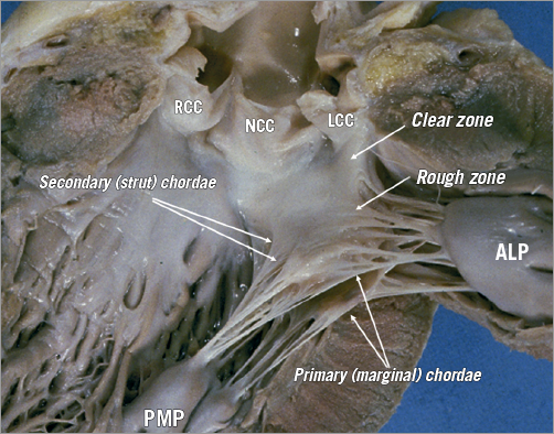
Figure 7. The leaflets of the MV are clearly divided into two regions, the clear zone which is at the base of the leaflets, thin and translucent, and the zone of coaptation, which is the distal rough and irregular zone, where numerous thick chordae originate and attach the leaflets to the PMs. Three types of chordae tendineae can be described. 1) The tertiary chordae normally originate directly from the LV and are attached to the base of the posterior leaflets and commissure. 2) The secondary chordae extend directly from the PM and are robustly (strut chordae) attached to the body of the leaflets, ventricular side. 3) The primary chordae (marginal) – the most numerous – are attached to the free margin of the leaflets and the space between them is never more than 3 mm. The attachment to the free margin is normally bifurcated or trifurcated. The commissural chordae, attached to the commissural tissue, are trifurcated giving them their characteristic fan-like appearance. ALP: anterolateral papillary muscle; PMP: posteromedial papillary muscle
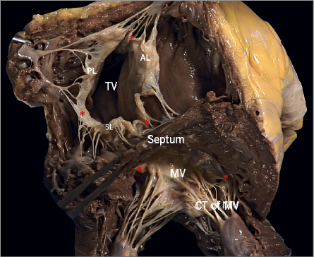
Figure 8. The commissures (red asterisks) of the atrioventricular valves are a functional entity consisting of two different structures: the base, which is attached to the annulus, and the free edge, which is supported by one or two fan-like chordae. The commissural leaflet is a small, triangular segment of leaflet tissue, which provides the continuity between the different valve leaflets.
The tricuspid leaflets
The TV comprises three leaflets, the anterior, the posterior and the septal, which are separated by three commissures (Figure 9). The septal leaflet is characteristic of the TV, with either direct chordal attachment to the septum or via the so-called Lancisi conal papillary muscle (PM). They are different in size and shape (Figure 8, Figure 10). The TV leaflets are thinner, more translucent and more fragile compared to the MV (Figure 10).
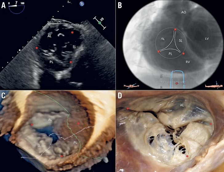
Figure 9. Multimodality imaging of the TV. A) Deep transgastric 2D TEE view, displaying the TV in short axis from the ventricular side. B) Same en face view derived from MSCT angiography. C) Short-axis atrial view of the TV on 3D TEE and during surgery (D). Red asterisks are the commissures. AL: anterior leaflet; LV: left ventricle; PL: posterior leaflet; RV: right ventricle; SL: septal leaflet
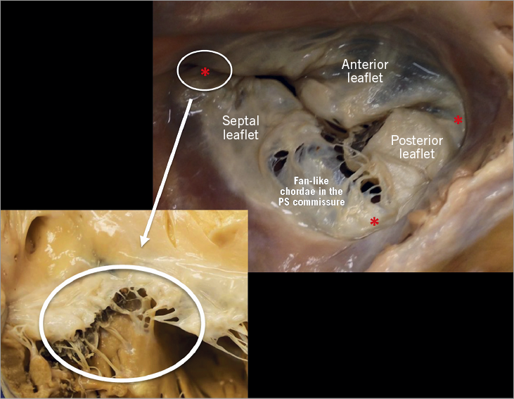
Figure 10. The anterior leaflet of the TV is larger than the posterior, which is larger than the septal leaflet. The anterior leaflet is primarily attached to the RVOT, the posterior to the muscular wall of the RV and the septal one to the septum. In comparison to the MV, few chordae are attached to the ventricular side of the leaflets. The commissures of the TV are three and separate the leaflets (red asterisks; close-up: anteroseptal commissure) with a free edge attaching the characteristic fan-like chordae.
INTERVENTIONAL PERSPECTIVES
Due to the different tissue property, the chance of damaging or tearing the TV leaflets is higher compared to the MV. This has to be considered in case of leaflet repair, as with the MitraClip in the tricuspid position: multiple grasping attempts in the TV (which are not infrequent due to the usually wider lack of coaptation in the TV compared to the MV) could be associated with leaflet or chordal damage.
SUBVALVULAR APPARATUS
The subvalvular apparatus of the MV is similar to that of the TV. It consists of two different structures, the papillary muscle (contractile function) and the chordae tendineae (elastic function).
PAPILLARY MUSCLES: MITRAL
The mitral PMs, which insert on the left ventricle (LV) free wall, are usually organised into two groups, the posteromedial and the anterolateral, situated just below the corresponding commissures (Figure 8, Figure 11, Figure 12). Apical displacement of the posteromedial PM secondary to lateral myocardial infarction is the most frequent mechanism to underline asymmetrical tethering and ischaemic MR.
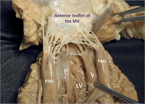
Figure 11. Each group of mitral PMs is implanted on the muscular wall of the LV, at a junction situated approximately 1/3 from the apex and 2/3 from the annulus. The left PMs can be either a single bulky PM with multiple heads or else several thinner PMs, from which arise numerous chordae attaching to the leaflets. The position varies little: the anterolateral PM is implanted at the junction between the septum and the posterior wall of the ventricle. The posteromedial PM is inserted on the lateral wall of the ventricle. The length is variable, ranging from 2 to 5 cm. No PMs attach to the left side of the ventricular septum.
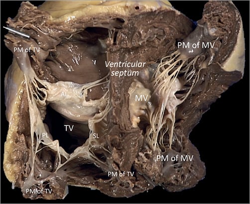
Figure 12. The PM arrangement supporting the three leaflets of the TV is different from that of the MV in the left ventricle. The anterior PM is the dominant one and is implanted on the anterior wall of the RV, near the apex, fusing with the moderator band. Its attachment may present two or three separate muscular formations, and the morphology is long and bulky with single or multiple heads. The posterior PM group could be single or double entity, with smaller multiple heads implanted on the posterior RV free wall.
PAPILLARY MUSCLES: TRICUSPID
The tricuspid PMs are inserted on the right ventricle (RV) wall and usually organised into three groups, anterior, posterior and septal (Figure 12). The anterior PM is dominant and is implanted on the anterior wall of the RV, near the apex, fusing with the moderator band (Figure 13).
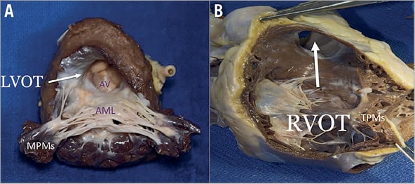
Figure 13. Anatomical comparison of left and right outflow tract. A) The septal surface of the LV may be considered to have a sinus portion, most of which is trabeculated, and a smooth outlet portion. The LVOT lies in front and to the right of the anterior mitral leaflet, corresponding to the inlet portion on the right ventricular side of the septum, and includes the atrioventricular septum. B) On the right side, the septal leaflet is the only one attached to the septum, but it leaves the RVOT free.
CHORDAE TENDINEAE: MITRAL
The chordae tendineae extend from the free margin to the PM and three types can be described – the basal chordae (tertiary), the intermediary chordae (secondary), and the marginal chordae (primary), which are the most numerous (Figure 8, Figure 11-Figure 13).
CHORDAE TENDINEAE: TRICUSPID
The tricuspid chordae tendineae, like the MV chordae, extend from the leaflet edges to the heads of the PMs. Basically, the TV having three leaflets, with the posterior often divided into further scallops, it presents a more complex chordal structure in comparison to the MV (Figure 8, Figure 12, Figure 13).
INTERVENTIONAL PERSPECTIVES
The main interventional issue related to the subvalvular apparatus is the risk of impingement of any device in the chordal apparatus, once the valve is crossed. In both the MV and the TV, the risk is higher in the commissural region, in which the density of chordae is at the maximum, while the middle of the valve is a chordae-free zone. This is particularly true for leaflet repair devices delivered antegradely, typically with the MitraClip. In the presence of a commissural lesion, the risk of clip impingement is particularly high and can lead to the impossibility of retrieving the device or chordal rupture with consequent worsening of the regurgitation. The risk of this complication during a MitraClip procedure appears to be similar in the mitral and tricuspid position. However, while in the MV this is normally encountered only in the context of specific anatomy (commissural lesion), in the TV the commissures are almost invariably the first therapeutic target (usually the anteroseptal): a first clip is implanted close to the commissure, where the coaptation deficit is minimum, in order to approximate the leaflets and facilitate the implantation of further clips on the coaptation line. Since the only location that allows leaflet grasping is at the real commissure, risk of impingement or chordal injury is always present in tricuspid clipping procedures. Similar to the leaflet, the chordal tissue of the TV is thinner and more fragile compared to the MV, and this may increase the risk of damage.
LEFT VENTRICLE, RIGHT VENTRICLE
ANATOMICAL DESCRIPTION
Left ventricle
The LV consists of a larger sinus portion, which supports the MV and includes the apex, and a much smaller outflow portion beneath the aortic semilunar valve. Contrary to the RV, the inlet and outlet valves of the LV lie juxtaposed within its base, and inflow and outflow portions are separated by a curtain represented by the anterior MV leaflet (Figure 13). Importantly, the LV trabeculations are characteristically fine compared with those in the RV.
Right ventricle
The RV has a large sinus portion that surrounds and supports the TV (inlet portion) and includes the apex and an infundibulum (outlet portion) that supports the pulmonic valve. The inlet and outlet valves of the RV, contrary to the aortic and MV, are thus widely separated by the crista ventricularis, minimising any risk of right ventricular outflow tract (RVOT) obstruction. The entire sinus portion of the RV and most of the infundibulum are coarsely trabeculated. The conduction system (bundle of His) perforates the central fibrous body closer to the RV side; therefore, it is very unlikely to damage this structure from the left, in comparison to the right side.
INTERVENTIONAL PERSPECTIVES
The close relationship between the anterior mitral leaflet, the aortic valve and the left ventricular outflow tract (LVOT) has important consequences: implantation of a prosthesis inside the native or repaired MV forces the anterior leaflet into an “open position”, that may encroach on the LVOT. This septal displacement of the anterior mitral leaflet is exaggerated when the aortic and mitral annular planes are acutely angulated, when the interventricular septum is hypertrophic, in the presence of an elongated leaflet, and when the valve implant extends or flares into the LV. On the other hand, the marked separation between the TV and the pulmonary valve by the crista supraventricularis and the wide-open angle between them make the risk of RVOT obstruction really low with any type of tricuspid device. While transapical LV access is frequently used for aortic and MV procedures (mainly valve replacement, which currently uses very large delivery systems that require precise coaxiality to be deployed, and chordal implantation), apical RV access presents several issues. Transapical access would provide coaxiality by definition and direct access to the TV, with a short route, and these aspects would make it ideal for transcatheter TV replacement in native anatomy, which uses a large delivery system. However, the thin and trabeculated RV wall makes this approach potentially risky, especially in the context of RV dilatation and dysfunction associated with functional TR. The arrhythmogenicity of this approach has to be assessed.
Conclusions
With the fast development of transcatheter TV therapies, physicians are facing a new challenging anatomical scenario. Some of the knowledge that has been generated during the development of MV devices can be applied to the TV, but a deep understanding of the peculiar anatomy of the TV and of the right heart chambers, and their differences compared to the MV, is fundamental to improving the safety and efficacy of these new therapies. The specific anatomical features of the TV, the suboptimal quality of intraprocedural TEE guidance and the absence of a standardised nomenclature remain major open issues to be addressed in TV intervention.
| Impact on daily practice A deep understanding of the peculiar anatomy of the tricuspid valve and of the right heart chambers, along with differences and similarities between the mitral and tricuspid valves, is fundamental to overcoming the specific challenges related to transcatheter tricuspid therapies. |
Conflict of interest statement
M. Taramasso is a consultant for Abbott Vascular and 4Tech. P. Denti is a consultant for Abbott Vascular, 4Tech and InnovHeart. F. Nietlispach is a consultant for Abbott Vascular, Medtronic and Edwards Lifesciences. R. Hahn is a consultant for Abbott Vascular and GE Healthcare. J. Schofer declares receiving travel support from Edwards Lifesciences. M. Leon is a non-paid member of the Scientific Advisory Board of Edwards Lifesciences and a consultant for Abbott Vascular and Boston Scientific. F. Maisano is a consultant for Abbott Vascular, Edwards Lifesciences, and Medtronic, and is a co-founder of 4Tech. The other authors have no conflicts of interest to declare.